MicroFusion in Intel CPUs.
15 Feb 2018
Contents:
- MicroFusion
- Why do we want MicroFusion?
- Fused/unfused domain
- Example 1: double fusion
- Example 2: half fusion
- Example 3: no fusion
- Unlamination
- Unlamination example 1
- Unlamination example 2
- Unlamination example 3
- Resources:
Subscribe to my newsletter, support me on Patreon or by PayPal donation.
My previous post about Instruction Fusion spawned lots of comments. What I really wanted to benchmark was fused assembly instructions, but it turned out that some other microarchitectural features were involved in that example, which I was not aware about.
With the help of Travis Downs and others on HackerNews I did more investigation on this and I want to summarize it in this post.
This post is not intended to cover all possible issues one can face. I rather want to present the high-level concept here. I did experiments only on IvyBridge architecture. In the end of the article I provide the links where you can find more details for particular architecture.
MicroFusion
There is a nice explanation of MicroFusion in Agner’s manual #3: The microarchitecture of Intel, AMD and VIA CPUs: An optimization guide for assembly programmers and compiler makers Chapter 7.6 (search for chapters with the same name for later architectures):
In order to get more through these bottlenecks, the designers have joined some operations together that were split in two μops in previous processors. They call this μop fusion.
The μop fusion technique can only be applied to two types of combinations: memory write operations and read-modify operations.
 ; Example 7.2. Uop fusion
 mov    [esi], eax               ; 1 fused uop
 add    eax, [esi]               ; 1 fused uop
 add    [esi], eax               ; 2 single + 1 fused uop
Why do we want MicroFusion?
Again, I will better quote Agner here:
μop fusion has several advantages:
- Decoding becomes more efficient because an instruction that generates one fused μop can go into any of the three decoders while an instruction that generates two μops can go only to decoder D0.
- The load on the bottlenecks of register renaming and retirement is reduced when fewer μops are generated.
- The capacity of the reorder buffer (ROB) is increased when a fused μop uses only one entry.
Fused/unfused domain
In order to understand all the benchmarks and the performance counters we need to know about fused and unfused domain.

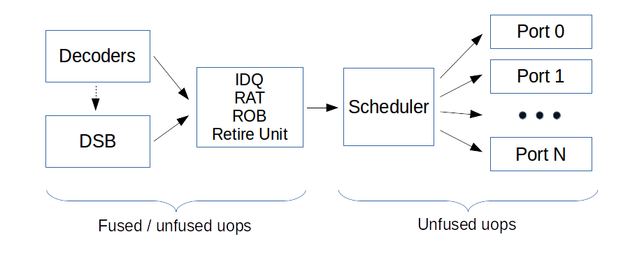
Fused domain indicates the number of uops generated by the decoders (including DSB). Fused uops count as one.
Execution units can’t execute fused uops, so such uops are split at the execution stage in the pipeline.
Unfused domain indicates the number of uops that go to each execution port.
Also there is description of this in the Agner’s instruction_tables.pdf, for example in Ivy Bridge section. Let’s look at the example for instruction add DWORD [rsp + 4], 1 in this manual for Ivy Bridge:

We can see here that there are 2 fused uops and 4 unfused uops (1+2+1). It means that after decoding 2 fused uops were produced. But on the execution stage they were split into 4 uops, 1 of which can go to either p0 (port 0), p1 or p5, 2 of them go to p2 or p3, and 1 go to p4.
In this post I will try to confirm this example (and more), but to do that we need to know which counters to use:
- Fused domain:
IDQ.DSB_UOPSandUOPS_RETIRED.RETIRE_SLOTS - Unfused domain:
UOPS_RETIRED.ALL
Description of the counters mentioned can be found here.
- IDQ.DSB_UOPS - Number of uops delivered to IDQ from DSB path.
- UOPS_RETIRED.RETIRE_SLOTS - Counts the number of retirement slots used each cycle.
- UOPS_RETIRED.ALL - Counts the number of micro-ops retired.
As of my knowledge, if the instruction stays fused in the Retire Unit we can count retired instruction both in fused and unfused domain. But if it is split in Retire Unit, those two counters will show the same number. If you don’t understand it - keep on reading, hope it will be clear when we will discuss un-lamination.
I did all experiments on Intel Core i3-3220T (Ivy bridge), however most of the examples will behave similar on later architectures (will be specifically mentioned).
Example 1: double fusion
add DWORD [rsp + 4], 1
Full code of the assembly function that I benchmarked can be found here. See also microbenchmarks integrated into uarch-bench.
Benchmark           Cycles   UOPS_RETIRED.RETIRE_SLOTS   UOPS_RETIRED.ALL
add [esp], 1        1.10     2.08                        4.08
No surprises in those results. We can observe the same behavior as shown in Agner’s tables. Decoded RMW instruction was decoded into 2 fused uops: load + op and write_addr + write_data. Number of unfused uops is 4, which also matches the results.
Example 2: half fusion
But let’s just change add [mem], 1 to inc [mem] and see what happens.
inc DWORD [rsp + 4]
Full assembly function, uarch-bench tests.
Benchmark           Cycles   UOPS_RETIRED.RETIRE_SLOTS   UOPS_RETIRED.ALL
inc [esp]           1.12     3.08                        4.08
Well, here we can see that there is only one fusion. I don’t know for sure which pair does not fuse, see more discussion on this on HackerNews discussion, comment by BeeOnRope.
Agner’s tables also confirm that (notice, the number of uops in fused domain is 3):

The same behavior holds for Skylake architecture.
Example 3: no fusion
Often times complex addressing mode (with multiple inputs) can cause no fusion to happen:
add DWORD [rsp + rcx + 4], 1
Full assembly function. See also microbenchmarks integrated into uarch-bench.
Benchmark           Cycles   UOPS_RETIRED.RETIRE_SLOTS   UOPS_RETIRED.ALL
add [esp + ecx], 1  1.40     4.18                        4.20
The measurements show that number of uops in fused and unfused domains are the same. You can find broader answer on StackOverflow, in particular:
SnB (and I assume also IvB): indexed addressing modes are always un-laminated, others stay micro-fused.
Unlamination
In order to show the case of un-lamination we will use the IDQ.DSB_UOPS counter, which also “operates” in fused domain.
Unlamination for SandyBridge is described in Intel® 64 and IA-32 Architectures Optimization Reference Manual in chapter “2.3.2.4: Micro-op Queue and the Loop Stream Detector (LSD)”:
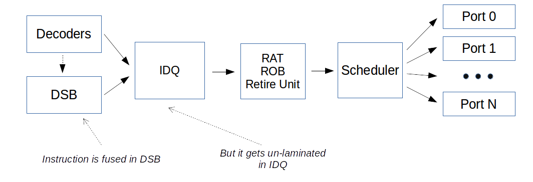
The micro-op queue provides post-decode functionality for certain instructions types. In particular, loads combined with computational operations and all stores, when used with indexed addressing, are represented as a single micro-op in the decoder or Decoded ICache. In the micro-op queue they are fragmented into two micro-ops through a process called un-lamination, one does the load and the other does the operation

Also I found very clear explanation on HackerNews thread. Especially, this note by BeeOnRope:
When instructions are fused at decode, but are “unlaminated” before rename, it usually has similar performance to no fusion at all (but it does save space in the uop cache), since RAT is more likely to be a performance limitation.
Unlamination example 1
I tried to put the instruction from the Intel optimization manual (section 2.3.2.4) in the tight loop and benchmark it:
.loop:
add     ebx, DWORD [rsp + rdi * 4 - 4]
dec     rdi
jnz .loop
Note, that now we are not measuring just this one add instruction, but instead the whole loop (showed below).
Benchmark              Cycles   IDQ.DSB_UOPS   UOPS_RETIRED.RETIRE_SLOTS   UOPS_RETIRED.ALL
add ebx, [esp + edx]   1.20     2.13           3.27                        3.30
Let me explain what is going on here. On each iteration 2 instructions were delivered from DSB to IDQ. They are one fused uop from add instruction and one uop macro-fused from dec and jnz. See explanation of MacroFusion in the Intel Optimization Manual, section “2.3.2.1 Legacy Decode Pipeline”.
However, micro-fused uop (from add) then was un-laminated (probably at IDQ) and further executed as two separate uops. That’s why we see the same number of uops retired for fused and unfused domain.
To understand the reason for this behavior, again, I will quote this great StackOverflow answer:
Why SnB-family un-laminates:
Sandybridge simplified the internal uop format to save power and transistors (along with making the major change to using a physical register file, instead of keeping input / output data in the ROB). SnB-family CPUs only allow a limited number of input registers for a fused-domain uop in the out-of-order core. For SnB/IvB, that limit is 2 inputs (including flags). For HSW and later, the limit is 3 inputs for a uop.
In this example add ebx, DWORD [rsp + rdi * 4 - 4] has 4 inputs: 3 registers and 1 FLAGS register. But the limit for SnB family is 2, that’s why it un-laminates in IDQ.
I think Agner’s instruction tables make no distinction between “full fusion” and “un-lamination”, so you should be aware about that. The number in the fused domain column always provide optimistic case, when no un-lamination happens.
Unlamination example 2
The same basically happens for RMW instruction:
.loop:
add     DWORD [rsp + rdi * 4 - 4], 1
dec     rdi
jnz .loop
Benchmark                 Cycles   IDQ.DSB_UOPS   UOPS_RETIRED.RETIRE_SLOTS   UOPS_RETIRED.ALL
add DWORD[rsp + rdi], 1   1.47     3.07           5.13                        5.13
In this example add DWORD [rsp + rdi * 4 - 4], 1 has 3 inputs: 2 registers and 1 FLAGS register. Again, the limit is exceeded.
Both 2 uops from add are fused in the DSB, but then they are un-laminated. I haven’t tested this on HSW and later architectures, but I assume there should be no un-lamination.
Unlamination example 3
To avoid un-lamination I tried to use simple addressing mode as below:
.loop:
add     DWORD [rcx], 1
add	rcx, 4
dec	rdi
jnz .loop
Benchmark                 Cycles   IDQ.DSB_UOPS   UOPS_RETIRED.RETIRE_SLOTS   UOPS_RETIRED.ALL
add DWORD[rcx] + add rcx  1.47     4.07           4.30                        6.33
Now there is no un-lamination happening, however the amount of executed uops is increased by one (this uop comes from add rcx, 4, which was ).
Resources:
- Intel® 64 and IA-32 Architectures Optimization Reference Manual section 2.3.2 “The Front End”.
- Agner Fog: The microarchitecture of Intel, AMD and VIA CPUs: An optimization guide for assembly programmers and compiler makers.
- Agner Fog: Instruction tables: Lists of instruction latencies, throughputs and micro-operation breakdowns for Intel, AMD and VIA CPUs
- Stack-overflow answer.
All content on Easyperf blog is licensed under a Creative Commons Attribution 4.0 International License